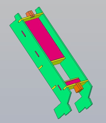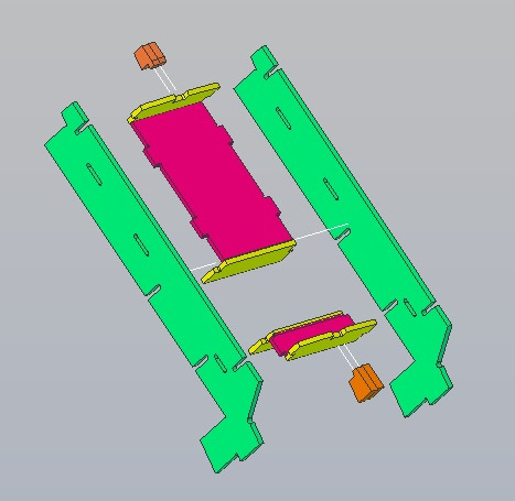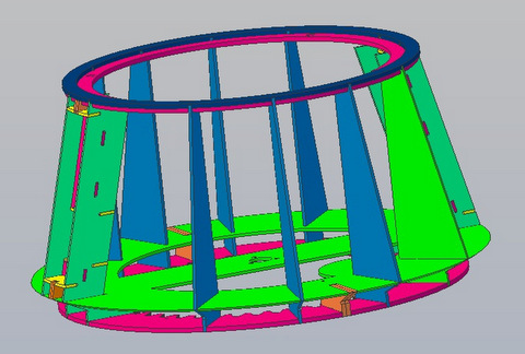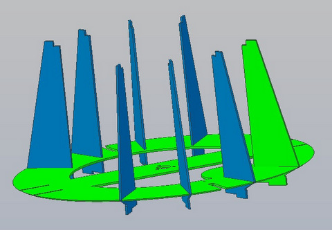
Image above links to a 3D .pdf file as does the image to the right |
[updated 07/29/18]
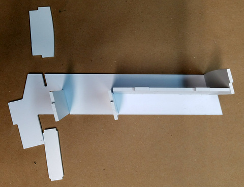
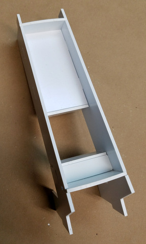
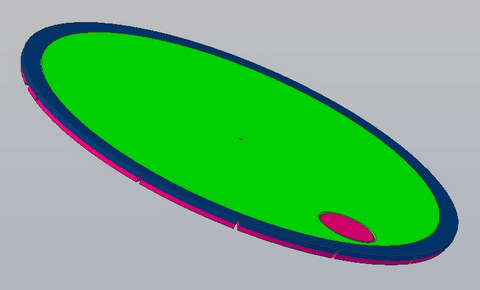
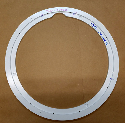
The head top is a sandwich of four pieces. Top inner, Top Outer and
Top Magnets and newly added, Top Periscope Socket. The fifth piece, the
Head Top Periscope Hat is not glued in place, set it aside. The Top Inner
is held in place by magnets, |
 | [New 07/29/18]
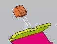
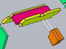
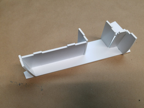
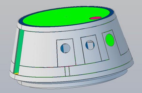
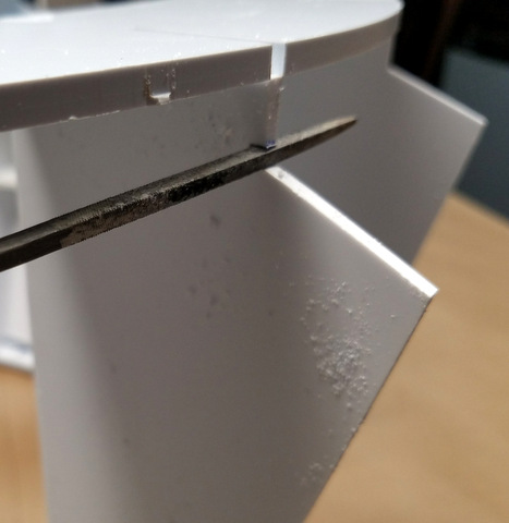
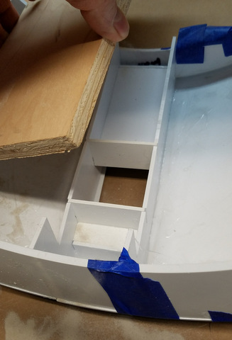
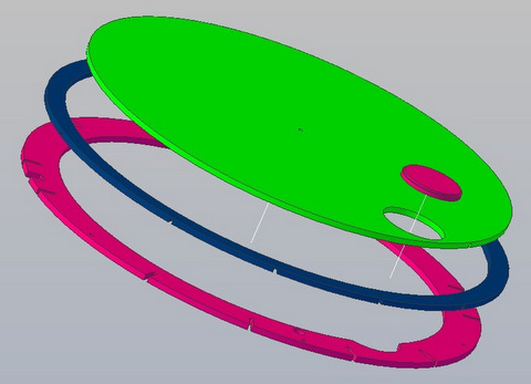
Left: The periscope socket, the lower of the two parts shown, is glued into the hole in the Head Top Inner.
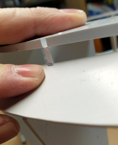
When flush with the Head Top, The Periscope "Hat" will have a .0625
panel line around it.That matches the other panel lines on the head.
The taper allows for a small mis-alignment between the Hat and the
Socket as the periscope decends into the head. |
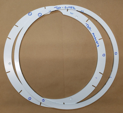 |
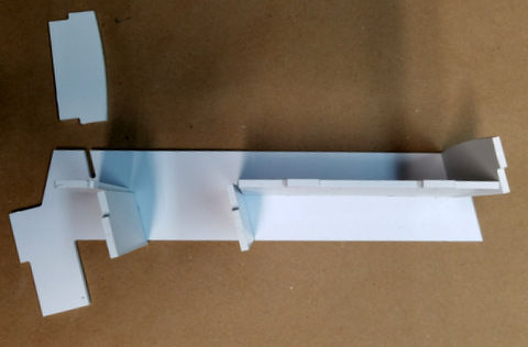
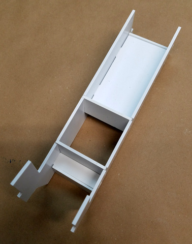
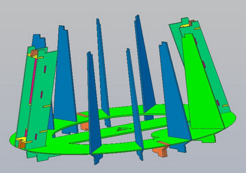
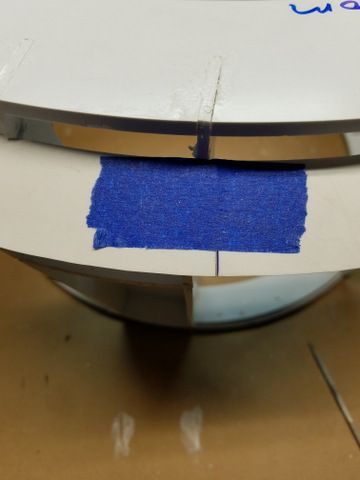
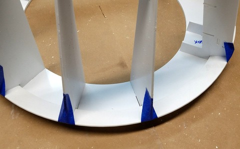
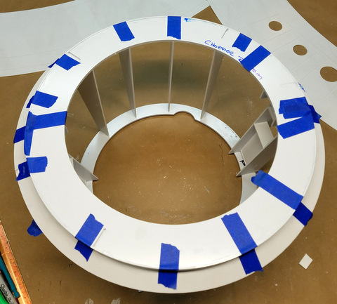
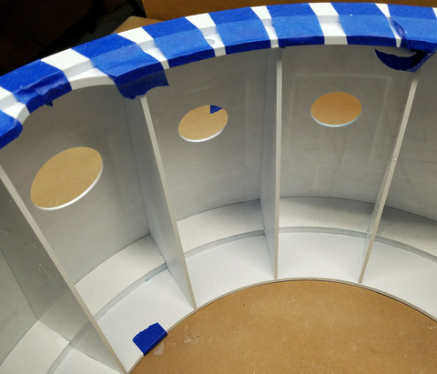
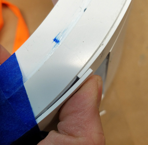
Left: The three sets of holes circled are
alignment holes for the assembly of the Head Top sandwich.
The hole in the Top Outer ring is a blind hole.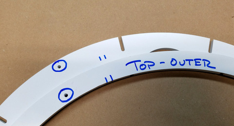
|
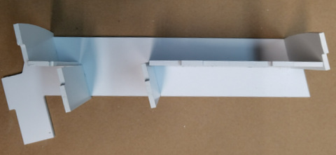
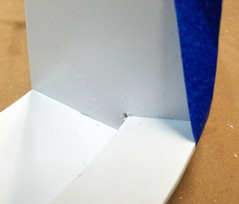
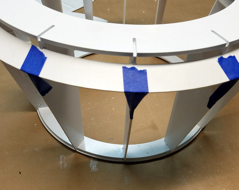
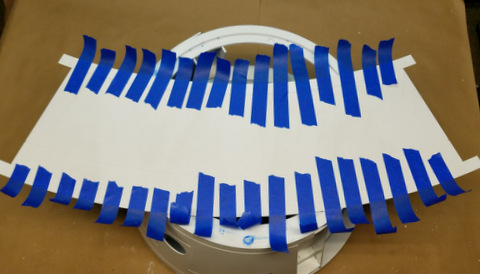
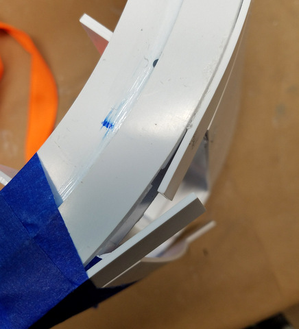
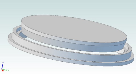
Below: use a small piece of filament
to align the two rings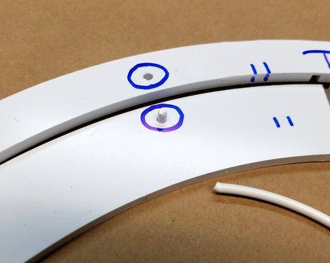
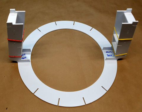
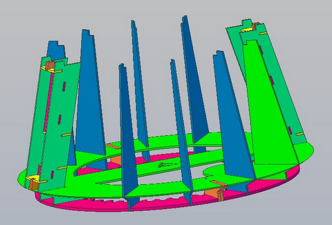
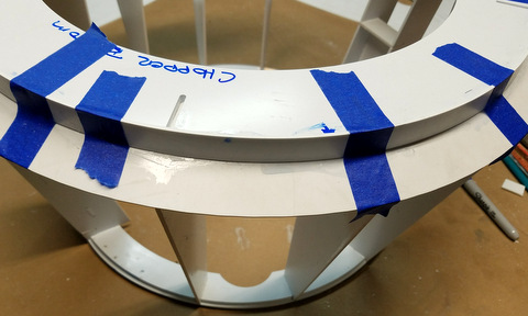
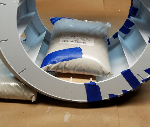
Left: before proceeding with the installation of the magnets (see
drawing files for magnet details) make small .0625 in holes in the
pockets where the magnets get installed in the Top Magnet ring. You'll
need the holes to push out a magnet in case you get the polarity wrong
:-( |
 |
Not Illustrated: Magnet Installation -
Install three magnets in the Head Top. Orientation (North/South pole)
is not important. Note there are no holes in the Head Top to allow you
to push the magnets out. Place three magnets on top of
those. They will naturally align (N/S) themselves with the first set.
Turn the Head top over and align it
with the Head Top Magnets ring (the periscope hole has to match up) If
you squeeze gently you should be able to force the loose magnets into
their pockets on the Head Top Magnets ring. |