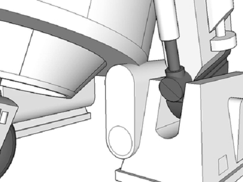
"One compromise that I already anticipated was the battery box
hitting the body when in 3-leg mode so I had to adjust the
height of the box closer to 6" instead of 6.5".
Picture Left & text above from TinyP's Build log
Chopper's Foot Shell & Apron, Drive & Battery Box
Background Discussion
Chopper's Battery Box was derived from Cleofett's .dwg drawing files. However, as noted by TinyP the original 6.625 in tall battery box hits the body in 3-leg mode.
|
See TinyP's build log, page 8, scroll down to
post #74 "One compromise that I already anticipated was the battery box hitting the body when in 3-leg mode so I had to adjust the height of the box closer to 6" instead of 6.5". Picture Left & text above from TinyP's Build log |
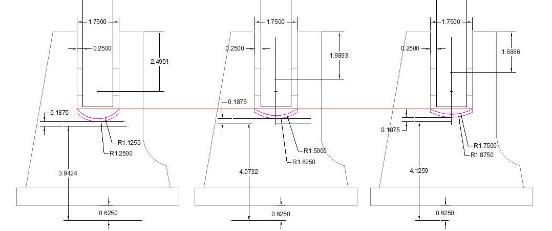
| In addition to changing the height of the Battery Boxes, In my version of Chopper's Battery Box the OD of the ends was changed from 2.625in OD to 2.75in OD. The change was driven by the cost of obtaining any kind of tubing that could be used to fabricate a 2.625in OD design. See the discussion about Acrylic Tubing costs for price comparisons. | |
| When I announced my intent to cut Chopper's parts from Extruded Acrylic tubing, a number of folks warned me that it was difficult to machine. While I don't disagree, it's both hard and brittle, but I've found it manageable. See here for how I've done it. | |
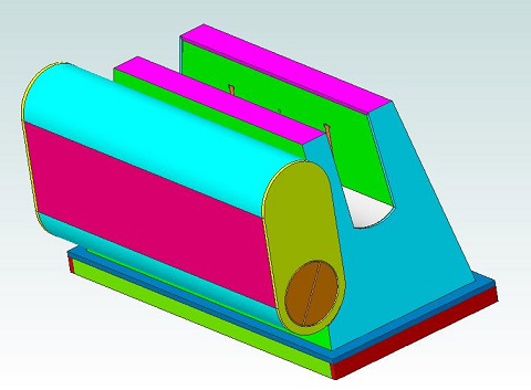 |
Except for the
rainbow of colors, this assembly looks like most other Chopper Foot
designs. The Image to the left links to a 3D .pdf file that allows you to rotate and zoom in on features of the design. |
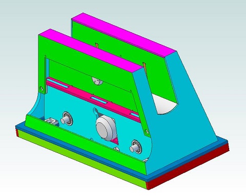
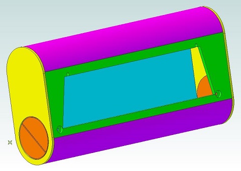 |
The Battery Box
hangs from two studs on the Foot Shell and is held in place by a pair
of magnets. Note that the cutout in the side of the Battery Box is not
symmetrical since the box is not centered on the Foot Shell. ie.
there's a Left Hand version and a Right Hand version. The Image to the left links to a 3D .pdf file that allows you to rotate and zoom in on features of the design. |
 |
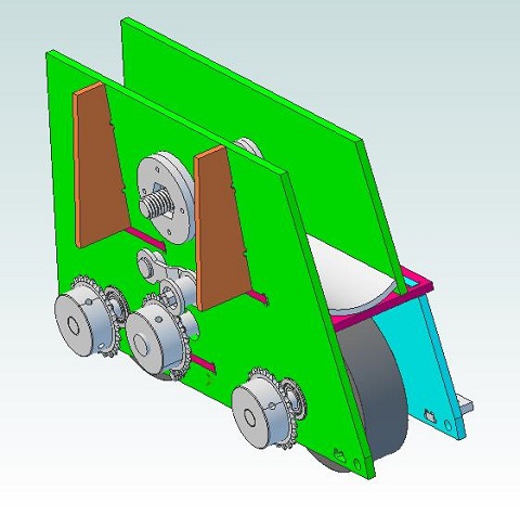
With the
Battery Box removed you can see how compact the drive components
actually are! All of the space in the Battery Box is available for the
LIPO battery and the ESC to drive the motor. The Image to the left links to a 3D .pdf file that allows you to rotate and zoom in on features of the design. |
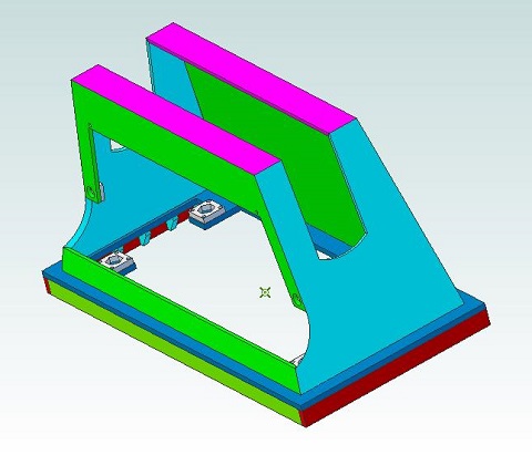 |
The Foot Shell
and Foot Apron are assembled separately and then glued together. The
Shell assembly slips onto the the Foot Drive Structural assembly and is
bolted in place from the underside of the foot. The Image to the left links to a 3D .pdf file that allows you to rotate and zoom in on features of the design. |
 |
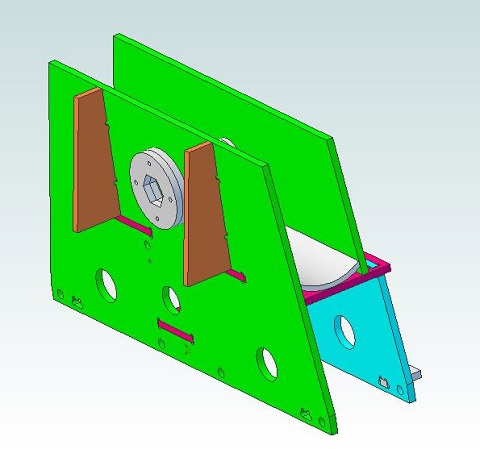
The Foot Drive
Structural components serve as the mounting point for the Drive parts
and provide the mounting point for the legs. Not shown on this drawing
is the chain that links the three sprockets. You can see the chain path
in the detailed assembly drawings. The Image to the left links to a 3D .pdf file that allows you to rotate and zoom in on features of the design. For a description of the Mechanical Components, a list of part numbers and designations, and the suppliers I used go to the Chopper Foot Drive - Mechanical Parts page |
 |
The last piece
in the onion, the Foot Drive Structural assembly shown here without the
Drive parts. The Image to the left links to a 3D .pdf file that allows you to rotate and zoom in on features of the design. |
| You
can download a .zip file
that includes both .pdf drawings of the parts for the Foot Shell,
Apron, Drive Structural & Battery Box components of the design. Follow the links here to the detailed descriptions of each of the components: Foot
Shell & Apron
Foot Drive Battery Box |
|