 |
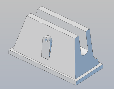
Foot - the design is symmetrical (almost - the battery boxes are not symmetrically mounted on the feet!) The image is linked to a 3D .pdf file You can download a zip file of all of the Chopper 3D .stp (step) files here. |
At least one builder has noted
that there's not much space in the foot for wheels! Here's an outline
of the problem and a suggestion for a solution.
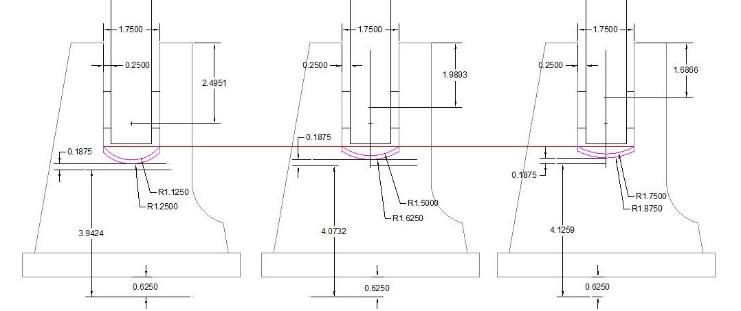
The drawing on the Left is a revised version of Cleofett's design. It's hard to find 1.1299 ID tubing. I've changed the curvature of the center mounting channel (shown in magenta) to 1.125 from it's original 1.1299 dimension and planned to use readily available Acrylic tubing. Then I checked the dimensions!
Allowing for a sheet of 3/16 in styrene under the tubing, and presuming a 5/8 in reveal of the wheels leaves only 3.9424 in of space! Not enough to use a 4 in wheel.
My next design iteration, in the center, utilizes a 1.5 in ID tube (center shifted up to keep the channel depth the same). That change was enough to get 4.073 of clearance. While it might work, It's a little tight for a 4 in wheel. My final design iteration was to use a 1.75 in ID tube, yielding 4.126 in of clearance.
If you've built a set of Chopper Feet with wheels I'm curious to know how you solved the space problem in your design!
If you put motors into your Feet I'd like to know which motors you used - the scooter motors I used in R2's feet will not fit!
Send me an email to fpirz (at) media (dash) conversions (dot) net!
If you put motors into your Feet I'd like to know which motors you used - the scooter motors I used in R2's feet will not fit!
Send me an email to fpirz (at) media (dash) conversions (dot) net!