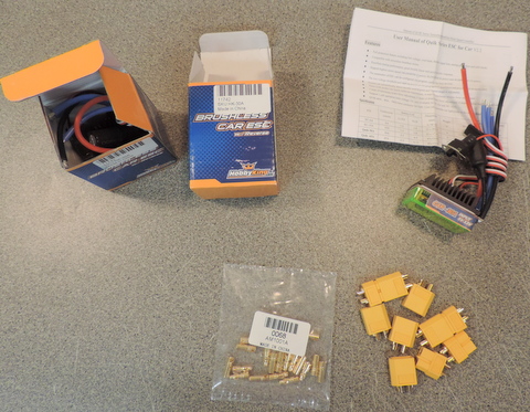
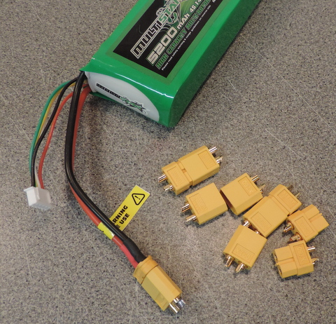
The batteries I'm using are fitted with XT60 Connectors. While the BLDC motor uses bullet connectors. It's handy to have a supply of the mating connectors on hand.
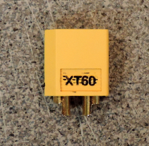
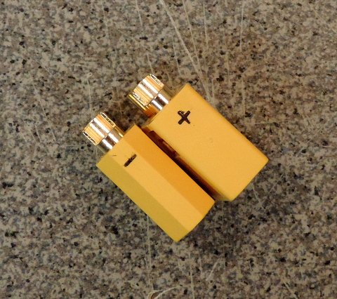
I've used a marker to highlight the molded in markings on the XT60's
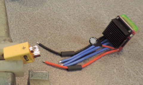
You need 3 hands for soldering. :-) note the shrink tubing slipped over the ESC's power wires. You don't want any high power connections exposed!
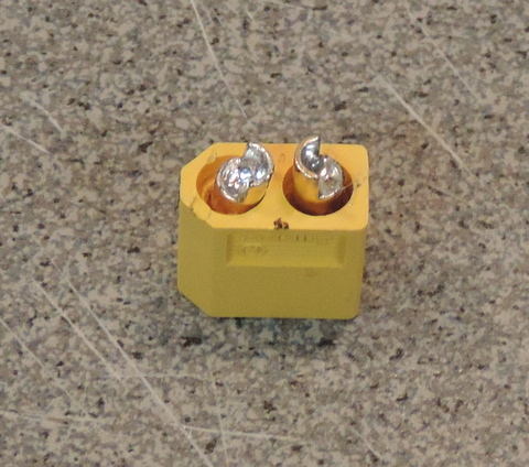
Left: Yes, it's possible to melt the plastic used in the XT60 Connectors, so work quickly.
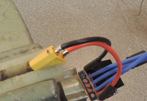
Above: once the connections are made let them cool. Then slide the heat shrink so that it covers the exposed connections and use a hot air gun to shrink the tubing. [If you don't wait for the connection to cool, the shrink tube will shrink on contact, before you have a chance to get into position!]
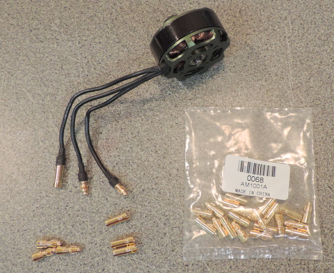
The motor uses male bullet connectors. I've slipped a mating female connector onto the leftmost motor connection just to check fit.
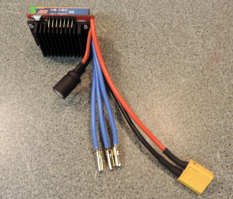
Solder three female connectors onto the ESC leads.
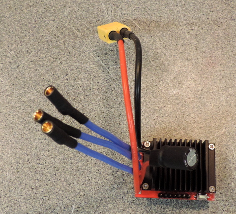
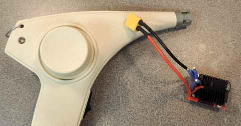
Not shown: Now that everything is connectorized, you can plug the parts together. Use a servo tester (or you R/C controller and it's reciever) to verify that everything works as expected!